Discover the signs of a and how to test it using , a multimeter, and a test light. Replace the fuse with ease after identifying the issue.
Visual Inspection
Burn Marks
When conducting a visual inspection of your electrical system, one of the key things to look out for is burn marks. Burn marks can indicate overheating or a short circuit within the system. These marks may appear as dark, discolored spots on the surface of electrical components or wiring. It is important to identify and address burn marks promptly to prevent further damage or potential safety hazards.
- Check all electrical connections and components for any signs of burn marks.
- Inspect the wiring for any discoloration or dark spots.
- Pay close attention to areas where components are tightly packed together, as overheating is more likely to occur in these areas.
Melting
Another visual indicator of electrical issues is melting. Melting can occur when the electrical system is overloaded or when there is a fault in the wiring. It is crucial to identify and address melting components promptly to prevent further damage or potential fire hazards.
- Look for any signs of melted plastic or insulation around electrical components.
- Check for any dripping or sagging of wires due to melting.
- Inspect the fuse box for any signs of heat damage or melting.
Breakage
In addition to burn marks and melting, breakage is another visual clue that there may be issues within the electrical system. Breakage can occur due to physical damage or wear and tear over time. It is important to replace any broken components to ensure the proper functioning of the electrical system.
- Inspect all wiring and components for any signs of breakage or damage.
- Look for any exposed wires or loose connections that may indicate breakage.
- Check for any cracked or broken electrical components, such as switches or outlets.
By conducting a thorough visual inspection and addressing any issues such as burn marks, melting, and breakage promptly, you can ensure the safety and efficiency of your electrical system. Remember, safety should always be a top priority when dealing with electrical systems.

Testing with Multimeter
When it comes to troubleshooting electrical issues, using a multimeter is a valuable tool that can help you pinpoint the source of the problem. Before you can start testing with a multimeter, you need to ensure that you have set it up correctly.
Setting up the Multimeter
Setting up a multimeter may seem daunting at first, but with a few simple steps, you can ensure that you are ready to start testing. Begin by selecting the appropriate settings on the multimeter. Most multimeters have a dial that allows you to choose the type of measurement you want to take, such as voltage, resistance, or continuity.
Next, you will need to insert the probes into the correct ports on the multimeter. The black probe typically goes into the COM port, while the red probe is inserted into the port labeled for the specific type of measurement you are taking.
Once the probes are securely in place, turn on the multimeter and ensure that it is functioning properly. You can test this by touching the probes together and verifying that the multimeter registers a reading of zero.
Testing Continuity
Continuity testing is a crucial step in troubleshooting electrical issues, as it allows you to determine if there is a complete path for the current to flow. To test for continuity, start by turning off the power source to the circuit you are testing.

Using the multimeter, set the dial to the continuity setting, which is often denoted by a sound wave symbol. This setting allows the multimeter to emit a beep when a complete circuit is detected.
Next, touch the probes to the two points in the circuit you want to test for continuity. If the circuit is complete, you will hear a beep indicating that there is continuity. If you do not hear a beep, there may be a break in the circuit that needs to be addressed.
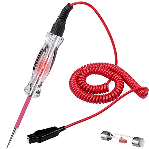
Using a Test Light
When it comes to diagnosing electrical issues in your vehicle, using a test light can be a handy tool. The test light procedure is relatively simple and can provide valuable insights into the health of your electrical system. By following the steps below, you can effectively use a test light to pinpoint any issues that may be present.
Test Light Procedure
To begin the test light procedure, you first need to ensure that the vehicle’s ignition is turned off to prevent any accidents or damage. Once the ignition is off, follow these steps:
- Connect the test light’s ground clip to a known good ground, such as the negative battery terminal.
- Touch the test light probe to the terminal or wire you want to test. If the test light illuminates, it indicates that there is power present at that point.
- Move the test light probe along the wire or component you are testing to check for continuity and proper power flow.
- If the test light does not illuminate at any point, it may indicate a break in the circuit or a faulty component.
By following these simple steps, you can effectively use a test light to identify any electrical issues in your vehicle’s system.
Interpreting Results
Interpreting the results of the test light procedure is crucial in determining the source of any electrical problems. If the test light illuminates at a specific point, it indicates that power is present at that location. On the other hand, if the test light does not illuminate, it may suggest a break in the circuit or a faulty component.
It is essential to move the test light probe along the wire or component being tested to ensure that power is flowing correctly throughout the system. If you encounter any inconsistencies or lack of illumination, further investigation may be necessary to identify and resolve the issue.
Checking Fuse Condition
Inspecting Fuse Element
When checking the condition of a fuse, the first step is to inspect the fuse element. This is where you will be looking for any signs of damage or wear that may indicate a blown fuse. Start by visually examining the fuse element for any burn marks, melting, or breakage. Burn marks can be an indication that the fuse has overheated, while melting or breakage may suggest a fault in the circuit.
- Look for any discoloration or dark spots on the fuse element.
- Check for any signs of warping or deformation.
- Inspect the fuse for any visible cracks or breaks.
Fuse Resistance Test
After inspecting the fuse element visually, the next step is to perform a fuse resistance test. This test will help determine if the fuse is functioning properly and has not blown. To conduct a fuse resistance test, you will need a multimeter set to the resistance mode.
- Remove the fuse from the circuit and set your multimeter to the resistance mode.
- Place the multimeter probes on each end of the fuse to measure the resistance.
- A reading of zero resistance indicates a blown fuse, while a reading of infinite resistance means the fuse is intact.
By inspecting the fuse element for any physical damage and conducting a resistance test, you can accurately assess the condition of the fuse. This information will help you determine if the fuse needs to be replaced and ensure the proper functioning of the circuit. Remember to always follow safety precautions when working with electrical components.

Replacing a Blown Fuse
Fuse Replacement Steps
When it comes to replacing a blown fuse, it’s essential to follow the correct steps to ensure safety and effectiveness. Here’s a simple guide to help you through the process:
- Step 1: Identify the Blown Fuse – The first step is to locate the blown fuse in your electrical system. This can typically be found in the fuse box of your home or vehicle.
- Step 2: Power Off – Before replacing the fuse, make sure to turn off the power to the circuit where the fuse is located. This will help prevent any accidents or electrical shocks.
- Step 3: Remove the Blown Fuse – Using a fuse puller or a pair of needle-nose pliers, carefully remove the blown fuse from its slot in the fuse box.
- Step 4: Check the Amperage – Before installing a new fuse, check the amperage rating of the blown fuse. It’s crucial to replace it with a fuse of the same rating to avoid overloading the circuit.
- Step 5: Install the New Fuse – Gently insert the new fuse into the empty slot in the fuse box. Make sure it fits securely and is positioned correctly.
- Step 6: Power On – Once the new fuse is in place, you can safely turn the power back on to the circuit. Test the circuit to ensure that the new fuse is functioning correctly.
Testing After Replacement
After replacing a blown fuse, it’s essential to test the circuit to confirm that everything is working as it should. Here are some simple steps to follow for testing after replacement:
- Step 1: Turn On the Device – If you replaced a fuse in an electronic device, plug it in or turn it on to see if it is functioning properly.
- Step 2: Check for Power – Use a or a test light to check for power in the circuit where the fuse was replaced. This will help you confirm that the new fuse is conducting electricity.
- Step 3: Monitor for Issues – Keep an eye on the circuit for any signs of overheating, unusual noises, or malfunctions. If you notice any issues, it may indicate a larger problem that needs to be addressed.
By following these steps for fuse replacement and testing, you can ensure the safety and efficiency of your electrical system. Remember to always prioritize safety and consult a professional if you encounter any difficulties during the process.